


I. Introduction: The Critical Need for Custom Heat Sink Technology
-
Catchy Hook: The relentless demand for smaller, faster, and more powerful electronic devices has made thermal management the single most critical challenge in modern engineering.
-
Defining the Core Problem: Standard, off-the-shelf heat sinks often fail to meet the stringent thermal and spatial requirements of high-performance applications (e.g., AI servers, 5G telecom, electric vehicles, industrial power electronics).
-
Introducing the Solution: This is where the custom heat sink becomes indispensable—a precisely engineered component tailored to an application's unique thermal profile, footprint, and environment.
-
Thesis Statement: This guide delves into every aspect of custom heat sink design and manufacturing, providing a roadmap for engineers to achieve optimal thermal performance and reliability.
-
II. Why Go Custom? The Limitations of Standard Heat Sinks
-
Space & Footprint Constraints: Standard parts rarely fit perfectly, leading to wasted space or inadequate cooling.
-
Thermal Mismatch: Off-the-shelf solutions are generalized; they cannot target specific hot spots or match the precise thermal resistance ($R_{th}$) required by the component.
-
Keyword Focus: Custom heat sink design optimization, thermal resistance requirements.
-
-
Airflow & Environmental Factors: Custom designs factor in the exact airflow (natural/forced convection) and ambient conditions (dust, vibration, humidity), which standard parts ignore.
-
Cost Efficiency in Volume: For high-volume production, a fully custom heat sink can often be more cost-effective than modifying or over-specifying a standard part.
-
Aesthetic & Mechanical Integration: Custom solutions ensure seamless mechanical integration and can meet specific aesthetic needs.
III. The Foundation of Custom Heat Sink Design: Key Thermal Parameters
This section is vital for establishing technical authority. Use bullet points and maybe a simple table.
-
Heat Load ($Q$ in Watts): The total power dissipated by the source component (TDP). This is the starting point for any custom heat sink project.
-
Maximum Junction Temperature ($T_{j,max}$): The maximum allowable temperature for the semiconductor junction, a non-negotiable limit for device longevity.
-
Ambient Temperature ($T_{a}$): The temperature of the cooling medium (air or liquid).
-
Thermal Resistance ($R_{th}$): The key metric.
-
Formula: $R_{th} = (T_{j,max} - T_{a}) / Q$.
-
A custom heat sink is specifically designed to achieve a target $R_{th}$ that is often much lower than what standard parts can offer.
-
-
Thermal Interface Materials (TIMs): A critical link. Discuss various TIMs (grease, pads, phase change materials) and their impact on overall $R_{th}$ in a custom thermal solution.
| Material Type | Thermal Conductivity (W/m·K) | Best Use Case |
| Aluminum (Al 6061/6063) | $\approx 160-200$ | Cost-effective, Extrusion |
| Copper (C110) | $\approx 380-400$ | High-performance, Small footprint |
| Heat Pipes (Copper/Water) | Up to $10,000$ | Spreading heat over a large base |
IV. Advanced Custom Heat Sink Fabrication Techniques
A deep dive into manufacturing processes, correlating each with specific design benefits and cost implications.
-
1. Extruded Custom Heat Sinks (Most Common):
-
Process: Pushing heated aluminum through a die.
-
Pros: Low cost, good performance, ideal for high volumes and simpler fin geometries.
-
Keyword Focus: Aluminum extrusion heat sinks, extruded custom heat sink profiles.
-
-
2. Forged Heat Sinks (MicroForging®):
-
Process: Stamping material under high pressure.
-
Pros: High-density, high-aspect ratio fins (taller and thinner), excellent for forced convection.
-
Cons: Higher tooling cost.
-
-
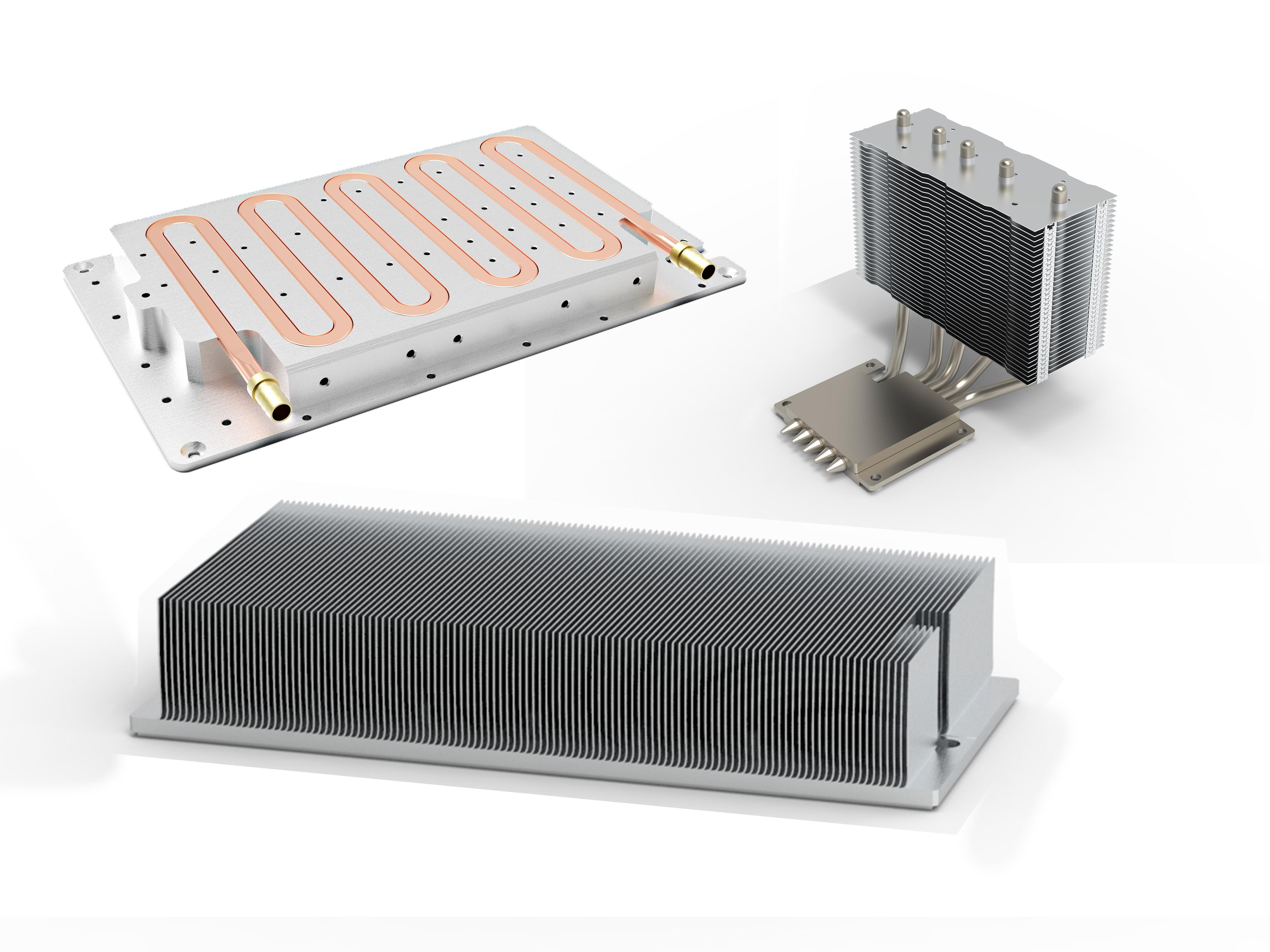
3. Skived Fin Heat Sinks:
-
Process: Cutting and bending fins from a single block of material (often copper).
-
Pros: Excellent thermal conductivity (no joint resistance), very fine fin pitch.
-
Cons: Limited height/size.
-
-
4. Brazed/Bonded Fin Heat Sinks:
-
Process: Bonding discrete fins (often copper) to a separate base plate.
-
Pros: Allows for very tall fins and mixed materials (e.g., copper base, aluminum fins).
-
Keyword Focus: Bonded fin heat sink manufacturers, high-performance heat sink solutions.
-
-
5. Machined Heat Sinks (CNC):
-
Process: Precision cutting from a solid block.
-
Pros: Perfect for complex, low-volume prototypes or extremely complex geometries.
-
Cons: High material waste, high cost.
-
V. Design Considerations for High-Performance Custom Heat Sinks
-
Fin Geometry & Optimization:
-
Straight Fins: Best for unidirectional airflow.
-
Pin Fins: Best for omni-directional airflow or heat sources with a small footprint.
-
Staggering & Slotting: Techniques to intentionally disrupt the boundary layer and increase the convection coefficient.
-
-
Heat Spreaders & Heat Pipes:
-
When the heat source is small and very hot (high heat flux), a base-integrated heat spreader (often copper) or embedded heat pipes are essential for efficiently moving heat across the heat sink base.
-
-
Material Selection: Deep-dive comparison (Al vs. Cu).
-
Aluminum is standard for mass/cost.
-
Copper is necessary for high heat flux areas due to its superior conductivity.
-
Hybrid designs (Copper slug embedded in an Aluminum base) offer a blend of performance and low weight.
-
-
Airflow vs. Pressure Drop: A key design trade-off. Tighter fin spacing improves surface area but increases air pressure drop, potentially requiring a more powerful (and louder/costlier) fan. Custom heat sink design balances this equation perfectly.
-
Surface Finish: Discuss the role of anodization (electrically insulating) and other coatings in optimizing radiation and preventing corrosion.
VI. The Custom Heat Sink Development Process: From CFD to Production
A step-by-step guide for potential clients.
-
Step 1: Requirements Definition: Defining $T_{j,max}$, $T_{a}$, Power ($Q$), spatial constraints, and mounting method.
-
Step 2: Computational Fluid Dynamics (CFD) Modeling:
-
The cornerstone of custom heat sink development. Simulating thermal performance and airflow before cutting metal.
-
Allows for rapid iterative optimization of fin count, height, and pitch.
-
-
Step 3: Prototyping & Testing: Creating a low-volume sample (often CNC machined) for real-world thermal testing and validation.
-
Step 4: Tooling & Mass Production: Moving to the final chosen manufacturing method (extrusion, forging, etc.) and implementing Quality Control (QC) checks.
VII. Real-World Applications of Custom Heat Sink Solutions (Approx. 200 words)
Provide concrete examples to illustrate the need for customization.
-
Telecommunications: 5G base stations with high-power RF amplifiers require extremely dense, high-performance, weather-resistant custom heat sinks.
-
Automotive: Electric vehicle battery management systems and power electronics (inverters/converters) demand rugged, vibration-proof, and often liquid-cooled custom solutions.
-
Data Centers & AI: Server CPUs and GPUs with ever-increasing TDPs need specialized two-phase (heat pipe/vapor chamber) custom heat sink assemblies.
-
Industrial Power: High-power LED lighting, motor controllers, and welding equipment.
VIII. Conclusion: Partnering for Thermal Success
-
Recap: Reiterate that in today's high-density electronics landscape, generic cooling is a recipe for failure. The custom heat sink is not a luxury, but a necessity for maximizing performance and longevity.
-
Final Call to Action (CTA): Emphasize the value of partnering with an experienced custom heat sink manufacturer that offers end-to-end services (CFD, prototyping, and various manufacturing options).
-
Closing Thought: Don't let thermal runaway be the Achilles' heel of your innovation. Invest in a precise, bespoke thermal solution.